
Assembly Basics for the ZX Spectrum
A downloadable project
This compendium will undoubtedly be appreciated by the generation that was approaching coding during the glorious 80's, moving from the arcade rooms to the magazine listings, aka the "bedroom coders". For the newbies, it could represent a glimpse into the past which led to the present.
Unlike the BASIC language, which uses a spoken-like syntax, the machine code is, at least at a first glance, not very intuitive. The study approach has almost always required a raw knowledge of the topic, starting with lessons about hexadecimal numbers and hardware diagrams. As a result, in many cases, beginners fail to achieve even the slightest result, losing their enthusiasm.
These short lessons start from practical examples and useful ROM calls, commenting line by line and making comparisons with BASIC instructions.
What is needed here is just a rudimentary knowledge of the BASIC language.
LET'S CHOOSE THE TOOLS
First of all, how do we manage to write a machine code program?
From an original machine, we should use a compiler software or, in case of a very short routine, directly write POKE instructions to load machine code into memory. For convenience, in this tutorial, we'll use emulators and PC tools:
- the ZX Spin emulator includes an Assembler editor;
- the BASin tool includes an Assembler editor and a tape creator useful to assemble external program parts in a single TAP or TZX file (e.g. useful to assemble loader, loading screen and the main program core);
- the Notepad++ editor needs no introduction, useful for saving code in asm format.
My personal choice focuses on the Spectaculator emulator by Jonathan Needle and the BASin tool by Paul Dunn (although it has some bugs).
COLOURS, PIXELS AND THE SCREEN MAP
Let's think the BASIC language as an interface to machine code, just as the Windows operating system is to DOS instructions. Back in the day, I loved studying examples from the ZX Spectrum manual or magazine listings.
Using the chosen emulator (or the original ZX Spectrum), let's type few lines to manage the screen attributes:
10 PRINT AT 2,0;"Value in 22528 was: ";PEEK 22528
20 POKE 22528,79
30 PRINT AT 3,0;"Value in 22528 now: ";PEEK 22528
The above BASIC program changes the paper colour attribute of the first top-left cell of the screen, by acting on the related memory address and changing its value (line 20).
The original value was 56 (it means black ink and white paper without bright), the new value is set to 79 (that is white ink and bright blue paper). Looking at the ZX Spectrum keyboard, we can see that the numbers from 0 to 7 are associated with colours (e.g. 1 for blue, 7 for white and 0 for black). Here's how to calculate colour attribute values:
INK colour + (PAPER colour * 8) + (BRIGHT * 64) + (FLASH * 128)
Note: INK paints the pixels inside the cell (in this case empty), while PAPER paints the cell background.
INK and PAPER can vary from 0 to 7, BRIGHT and FLASH can be 0 (inactive) and 1 (active). So, to calculate white ink with bright blue paper:
7 + (1 * 8) + (1 * 64) + (0 *128) = 79
If we want to add a FLASH effect:
7 + (1 * 8) + (1 * 64) + (1 *128) = 207
Try to change the value in line 20 from 79 to 207 and see the result!
The ZX Spectrum screen is made up of 32 columns horizontally and 24 lines vertically (of which the last 2 lines at the bottom are used for the command prompt and return service messages following the execution of a program). That is, 768 characters cells in total.
Each of these cells has a specific memory address, both for the colour attributes and for the content in pixels:
- the memory address range for the pixels starts from 16384 and ends at 22527;
- the memory address range for the colour attributes starts from 22528 and ends at 23295.
FIRST LINES IN MACHINE CODE
Now let's see how to transform the same POKE instruction in Assembly. Let's enter in the BASin Assembler editor, where it's possibile to store the code directly in memory to test it, or export to a .bin file, in order to use it later (e.g. with another emulator).
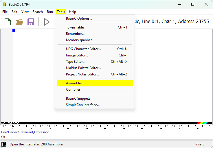
To translate "POKE 22528,79" in machine code, let's write these lines in the Assembler editor:
org 64000
ld hl,22528  ; in BASIC it's like saying: LET hl=22528
ld a,79      ; in BASIC it's like saying: LET a=79
ld (hl),a    ; in BASIC it's like saying: POKE hl,a
ret          ; in BASIC it's like saying: STOP (or RETURN)
Here it is! Let's explain the instructions:
- "org" sets the starting address where the routine will be stored. We can change it freely by choosing a RAM ("Random Access Memory") range, depending on the machine we're using:
- free RAM for a 16K ZX Spectrum: from 23755 to 32599
- free RAM for a 48K ZX Spectrum: from 23755 to 65367
- "ld hl,22528" sets the desired memory address storing the number into the 16-bit register "hl", which is mainly used for addressing;
- "ld a,79" loads the desired value into the 8-bit accumulator "a";
- "ld (hl),a" assings the value stored in the accumulator to the address stored in the "hl" register (if a 16-bit register was associated with a memory address, to load a value it's necessary to write it between brackets);
- "ret" ends the routine execution.
The text following the semicolon is ignored during execution, it's just useful for commenting the code.
Once finished writing the code, in order to verify and store it into memory, let's assemble through the path "File / Assemble / To Memory":
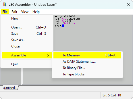
If the code has no errors, BASin will return a confirmation message including the length of the routine. In this case, the instructions weigh 7 bytes.
Now the code is stored into the Spectrum memory. To activate it, we need a call to the chosen address in the "org" instruction. In the BASIC editor, we can execute the stored routine this way:
CLEAR 63999: RANDOMIZE USR 64000
The result will be the same we've seen in the first BASIC program: the first top-left cell of the screen has a bright blue background!
Now let's go in depth on some important concepts.
REGISTERS AND LD
There are two kind of registers:
- 8-bit registers: can handle 1 byte, that is, values from 0 to 255
- 16-bit registers: can handle 2 bytes, that is, values from 0 to 65535
These are some of the most relevant 16-bit registers (2 bytes each):
af – bc – de – hl
The above 16-bit registers can be splitted into single 8-bit registers (1 byte each):
a – f – b – c – d – e – h – l
Those who come from BASIC could associate registers with variables. But unlike the latter, in the Assembler language some registers (such as “a” and “b“) have specific uses, and not all combinations are possible, since some instructions work exclusively with specific registers.
The “a” register is the most important, it’s called the accumulator.
As seen in the above routine, the easiest task is to load a value into a register through the "ld" instruction:
ld a,0     ; loads the value 0 into register "a"
ld b,2     ; loads the value 2 into register "b"
ld de,257  ; loads the value 257 into register "de"
ld a,d     ; loads the current value of "d" into "a"
The register “hl” is mainly used for addressing, this means it usually points to a memory location.
ROM, RAM AND THE MEMORY MAP
ROM is the "Read Only Memory" area, where resides the system core of the computer. It could be compared to the folders of an operating system, but in the case of ROM it isn't physically possible to overwrite data, but only to access it for reading.
In the ROM area reside all the system routines linked to the BASIC commands. We'll see how to call the same routines directly in machine code, using the "rst" or "call" statements.
RAM is the precious available space to store custom machine code programs.
So, by collecting all the above informations, we can build the memory map of the ZX Spectrum:
- 00000 ~ 16383 ROM
- 16384 ~ 22527 screen pixels
- 22528 ~ 23295 screen attributes (INK, PAPER, BRIGHT, FLASH)
- 23296 ~ 23754 system reserved
- 23755 ~ 32599 free memory (16K)
- 32600 ~ 32767 UDGs (16K)
- 23755 ~ 65367 free memory (48K)
- 65368 ~ 65535 UDGs (48K)
A review from the BASIC programming manual: UDGs are the "User Defined Graphics", that is an area dedicated to 21 redefineable characters.
Each character (or screen cell) is drawn in a grid of 8x8 pixels and weighs 8 bytes (one value for each of the 8 lines). So the total available space for the 21 UDG characters is 168 bytes. Here's a detail of a character cell and the relative values for each line:
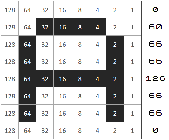
If it isn't necessary to use UDGs (normally used in BASIC programs in order to have a custom graphic set), this small range of memory can be dedicated to a machine code program without problems.
A REFERENCE TABLE
In the BASIC Programming manual there's one of the most consulted sections by Assembly coders: the "Appendix A". There we find a list of 256 numbers (from 0 to 255), where each of them represents a machine code instruction, a chatacter (numbers, letters, symbols) or a BASIC command.
E.g. the number "22" is associated with both the BASIC command "AT" and the machine code instruction "ld d,n".
So, in machine code programming, as the syntax of the project develops, the numbers could have three different meanings:
- a machine code instruction;
- a reference to a BASIC command (or character);
- the value itself.
Only one of these choices will be the valid one, depending on how the code is developed.
Let's take the "ld d,n" instruction for example: some machine code instructions forcefully require to be followed by 8-bit values (marked as "n") or 16-bit values (marked as "nn", for the numbers greater than 255) or, in other cases, by other instructions, in order to correctly execute the requested routine.
So, if we write "ld a,79", the Assembler will translate the instruction into machine code numbers in sequence "62" and "79".
Using the "Appendix A" table reference, let's translate our first routine:
org 64000    ; custom memory address where the routine is stored
ld hl,22528  ; assembler code: 33,0,88 (3 bytes)
ld a,79      ; assembler code: 62,79   (2 bytes)
ld (hl),a    ; assembler code: 119     (1 byte)
ret          ; assembler code: 201     (1 byte)
If we want to write the same routine in BASIC, through POKEs:
 5 REM  ld hl,22528
10 POKE 64000,33: POKE 64001,0: POKE 64002,88
15 REM  ld a,79
20 POKE 64003,22: POKE 64004,79
25 REM  ld (hl),a
30 POKE 64005,119
35 REM  ret
40 POKE 64006,201
The number "22528" is translated into the pair of values "0" and "88", let's see how the calculation happens: 22528 / 256 = 88, remainder is 0.
So, to get the pair of values for the numbers in the range between 256 and 65535, just take for the first one the remainder and, for the other, the result of a division by 256.
Naturally there's no need to carry out these calculations while writing in the Assembler editor, however, it's essential to know how the translation into machine code occurs.
PRINT SINGLE-BYTE CHARACTERS AND STRINGS
Let's try a routine to print characters on screen, always keeping in sight the control codes and character codes listed in the Appendix A:
org 64000
ld a,2     ; screen setup at top
call 5633  ; ROM call for screen setup
;
ld a,"!"   ; define a control code or character
           ; ("!" could be replaced by the code 33)
rst 16     ; print single-byte control code or chr
;
ld de,txt1 ; string data stored in label "txt1"
ld bc,11   ; string length
           ; (every value is counted as a single-byte)
call 8252  ; ROM call for PRINT AT
;
ld de,txt2 ; string data stored in label "txt2"
ld bc,17   ; string length
           ; (every value is counted as a single-byte)
call 8252  ; ROM call for PRINT AT
ret
;
; label "txt1" defines a string separated by a line-break
; 13=ENTER (control code for line-break)
txt1 defb "Hello",13,"World"
;
; label "txt2" defines colours, position and text string
; 16=INK, 17=PAPER, 22=AT (row,column)
txt2 defb 16,2,17,6,22,3,11,"Goodbye..."
The ROM call at 5633 is the screen setup, needed to print characters at a specific position. It requires the accumulator to be loaded with "0", "1" or "2", where:
- "ld a,0" or "ld a,1" set the screen-bottom (rows 22 to 23 numbered as 0 and 1);
- "ld a,2" sets the screen-top (rows 0 to 21).
The ROM call at 16 prints a character at the first available position, starting from top-left (AT 0,0) when the position isn't specified. It requires the accumulator to be loaded with a control value or a character ("ld a,n").
The ROM call at 8252 prints a string. It requires the pair of 16-bit registers "de" and "bc":
- "ld de,nn" where nn could be text or a custom string label;
- "ld bc,nn" where nn is the string length.
The defb instruction is preceded by a custom label and followed by a list of character codes, control codes or text enclosed into double quotes. Every defb value is counted as a single-byte.
The first call at 8252 prints the text including a line-break, without a specific position or colour attributes, while the second call at 8252 prints a text specifying the colour for INK (red), PAPER (yellow) and the AT values (row 3, column 11).
Notes:
- the Assembly code is always processed sequently, one instruction after the next;
- the "rst" instruction is used to call 8-bit memory addresses (0 ~ 255), while the "call" instruction is needed for 16-bit addresses (0 ~ 65535);
- the call at 5633 is required (once) before the calls at 16 / 8252 in order to setup the screen;
- the defb data can be written at the bottom of the routine, after the closing ret statement.
KEYPRESS, COMPARISONS, JUMPS (INKEY$ / IF / THEN / ELSE / GO TO)
Let's go on with another practical routine, how to detect a keypress. In this routine we'll come across other useful instructions used for comparisons, loops and jumps.
lastk equ 23560
      org 64000
      ld hl,lastk ; LAST K system variable
      ld (hl),0   ; put null value there
loop  ld a,(hl)   ; new value of LAST K
      cp 0        ; is it still zero?
      jr z,loop   ; yes, so no keypress
      ret         ; key was pressed
The equ instruction represents a shortcut whose label is associated with a specific memory address. This way the custom labels become variables and they can be set at the beginning, before the org statement.
The reserved memory area 23552 ~ 23734 is dedicated to the so-called "system variables", in the address 23560 (named "LAST K") the system stores the code of the last pressed key.
The instructions before the "loop" label say "POKE 23560,0", resetting the system variable. When a key is pressed, the relative code is stored into the "LAST K" system variable.
The following instructions say "IF (PEEK 23560) = 0 THEN GOTO (loop) / ELSE STOP", checking if any key is pressed. The check loops until the value into 23560 changes:
ld a,(hl) - the first instruction in the loop cycle, keeps the accumulator constantly updated, loading the content of the LAST K system variable (whose address is associated with the hl register);
cp 0 - the "cp" instruction compares the content of the accumulator (the "a" register) with a number or another 8-bit register;
jr z,loop - the "jr z,label" instruction is the jump to the point where the label is placed, It's equal to "GO TO" in BASIC. In this case, the "z" parameter establishes a check on the equality of values, like saying "IF a = n THEN ...".
We’ve seen how to test for equality, now let’s use other conditionals to check for further comparisons (less than, greater than):
...
ld b,7
ld a,5
cp b         ; is (a = 7)?
jr z,label1  ; if (a = b) then go to label1
jr nc,label2 ; if (a > b) then go to label2
jr c,label3  ; if (a < b) then go to label3
jp label4    ; no conditions, just go to label4
...
So the "cp" instruction compares the register "a" with a given number (or another 8-bit register, like above) and precedes the jump commands.
Notes:
- the jump conditional statements (z, nc, c) are placed after the "jr" or "jp" instructions;
- when the code between the label and the jump command exceeds 128 bytes, "jr" is no longer allowed (the Assembler editor will return an error); for a jump range greater than 128 bytes, the "jp" instruction is required;
- the "jr" instruction weights 1 byte less than "jp".
Let's combine the topics of the last two routines for a recap, adding a new ROM call to colour the border:
lastk equ 23560
      org 64000
      ld hl,lastk ; LAST K system variable
      ld (hl),0   ; put null value there
;
      ld a,2      ; set a red colour
      call 8859   ; ROM call to set BORDER
;
loop  ld a,(hl)   ; new value of LAST K
      cp 49       ; key "1" is pressed?
      jr z,print  ; yes, go to label "print"
      jr loop     ; no, repeat the check
;
print ld a,2      ; set top screen
      call 5633   ; ROM call for screen setup
      ld de,txt   ; define text string
      ld bc,29    ; define bytes length
      call 8252   ; ROM call for PRINT AT
      ret
;
;     16=INK, 17=PAPER, 18=FLASH, 19=BRIGHT
txt   defb 16,2,17,6,18,1,19,1
;     22=AT (row,column)
      defb 22,11,6,"KEY 1 WAS PRESSED!"
This time the routine waits for the pressing of the specific key "1" (equivalent to code 49 as indicated in the Appendix A).
ADD AND SUBTRACT
The "inc" and "dec" instructions are used to add or subtract a single unit, they work both with 8-bit and 16-bit registers. Here're some examples:
...
ld a,5
inc a         ; a = 5 + 1
ld b,a
dec b         ; b = 6 - 1
...
ld bc,1000
inc bc        ; bc = 1000 + 1
inc bc        ; bc = 1001 + 1
...
The "add" instruction is used to add a number from a register. Examples on how it works directly with registers:
...
ld a,1
add a,9      ; add 9 to 1
...
ld hl,16384
ld bc,6144
add hl,bc    ; hl = hl + bc, so now hl = 22528
...
Examples on how "add" works indirectly with other registers:
...
ld b,8
add a,b    ; a=b
add a,5    ; a=b+5
ld b,a     ; b=b+5
...
ld bc,46
ld h,b     ; since "ld hl,bc" isn't allowed,
ld l,c     ; split values to transfer bc into hl
...
ld bc,52
add hl,bc  ; hl=bc+52
...
Now you know how to add, what about subtracting?
sub n ; means a=a-n
It’s only possible to "sub" from "a" (the accumulator), therefore all the other subtractions must be made inderectly, like this:
...
ld a,16    ; a=16
sub 5      ; a=a-5, so now a=11
ld b,65    ; b=65
ld a,b     ; a=65
sub 6      ; a=65-6, so now a=59
ld b,a     ; b=59
...
THE STACK, PUSH, POP
What’s the stack? Let’s just imagine it as a container, empty at the beginning, where layers of data are stored.
There may be the need to use the same registers multiple times for different subroutines. In these cases the stack helps to temporarily place the register in a layer via the "push" instruction, so that it can be used again from scratch. Once the new subroutine is finished, the previous value is restored via the "pop" instruction, emptying the layer.
So "push" will place a value on top of the pile, while "pop" takes the value off the top of the pile.
...
ld bc,10  ; bc = 10
push bc   ; places 10 into the first layer of the stack
          ; now the stack looks like this:
          ; [ 10 ]
ld bc,5   ; bc = 5
          ; new value for bc, register is reused
          ;
ld de,15  ; de = 15
push de   ; stores 15 at the top of the stack
          ; now the stack looks like this:
          ; [ 15 ]
          ; [ 10 ]
ld de,20  ; de = 20
          ; new value for de, register is reused
          ;
pop bc    ; unloads the value of bc from the stack
          ; so now the stack looks like this:
          ; [ 15 ]
          ; and bc = 10 again
pop de    ; unloads the value of de from the stack
          ; so now the stack is empty
          ; and de = 15 again
          ; (two push and two pop instructions)
...
So, as said, in a practical use, by "pushing" the registers in the stack, the same registers can be used for other subroutines. Then, it's important to "pop" the restoration of their initial values in the main routine.
Notes:
- to avoid the risk of a crash or unwanted results, it’s important not to exit the routine before "popping" from the stack all the stored values;
- the "push" and "pop" instructions only work with these 16-bit registers:
- af – bc – de – hl.
THE DJNZ CYCLE (FOR / NEXT)
The "djnz label" instruction could be compared to the "FOR/NEXT" cycle in BASIC. It combines the instructions "dec" and "jr nz,label" in a loop cycle: the "djnz label" instruction acts on the register "b" decreasing it by one unit, then jumps to the label section. So, in this case, the "b" register acts as a counter.
Let's see how it works along with other instructions:
     ...
     ld a,0
     ld b,15   ; n. of times for the loop to execute
loop push bc   ; push "b" at the top of the stack
     ld b,4    ; load a new value in register "b"
     add a,b   ; a=a+4
     pop bc    ; restore "b" from the stack
     djnz loop ; b=b-1, end as soon as "b" reaches zero
     ...
Notes:
- "djnz" provides for decreasing the "b" register by one unit;
- if the value of the register "b" has to change inside the cycle, then the stack will help;
- "djnz" always uses the register "b".
A COMPLETE ROUTINE
Let's compile a routine named "chequered attributes" which includes some new ROM calls. First it cleans the screen, then it draws a chequered area (background attribute colours) and after the rendering it awaits for a keypress (PAUSE 0) producing an acoustic signal (BEEP):
       ; chequered attributes
       ; (CLS, POKE, FOR/NEXT cycle, PRINT AT, PAUSE, BEEP)
       ;
       org 64000
       ; clear the screen
       call 3435   ; ROM call for CLS
                   ; no registers required
       ;
       ; set the start cell and the cycles
       ld hl,22528 ; top-left screen attribute address
       ld a,12     ; cycle for 2 blocks to complete 24 rows (*)
       ;
       ; draw a row of black and white blocks
loop   ld b,16     ; cycle for 2 blocks to complete 32 columns
row1   ld (hl),0   ; load the value for black
       inc hl      ; increment address
       ld (hl),127 ; load the value for bright white
       inc hl      ; increment address
       djnz row1   ; decrement "b", cycle till "b" reaches zero
       ;
       ; draw a row of white and black blocks
       ld b,16
row2   ld (hl),127
       inc hl
       ld (hl),0
       inc hl
       djnz row2
       ;
       ; repeat the cycle 12 times (*)
       dec a       ; decrement accumulator (*)
       jr nz,loop  ; cycle till accumulator reaches zero
       ;
       ; print a flashing message "PRESS A KEY!"
       ld a,2      ; set top screen
       call 5633   ; ROM call for screen setup
       ;
       ld de,txt1  ; string data stored in label "txt1"
       ld bc,25    ; string length
                   ; (every value is counted as a single-byte)
       call 8252   ; ROM call for PRINT AT
       ;
       ; wait for a keypress using PAUSE 0
       ld bc,0
       call 7997   ; rom call for PAUSE nn
                   ; requires the duration set in "bc" register
                   ; a value set to "0" waits for a keypress
       ;
       ; perform an acoustic signal
       ld hl,390
       ld de,80
       call 949    ; rom call for BEEP nn,nn
                   ; requires "hl" for the pitch value
                   ; (lower = higher tone, affects the duration)
                   ; and "de" for the duration
       ;
       ret
       ;
       ; define string parameters and text
       ; 16=INK, 17=PAPER, 18=FLASH, 19=BRIGHT, 22=AT (row,column)
txt1   defb 22,11,8,19,1,16,2,17,6,18,1,"PRESS ANY KEY!"
Note: you can safely skip writing comments preceded by a semicolon...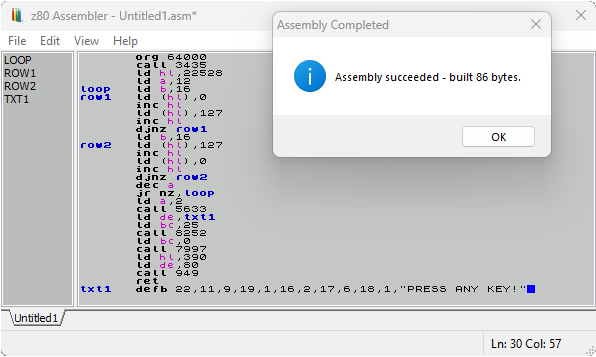
...now import the routine into memory (through a .bin file or assembled directly into memory in BASin) and run it from BASIC:
CLEAR 63999: RANDOMIZE USR 64000
enjoy the result!
SUMMING UP...
Let's recap some BASIC commands and the corresponding machine code instructions:
; BASIC "POKE nn,n"
; *****************
ld hl,nn
ld (hl),n   ; or: ld a,n / ld (hl),a
;
;
; BASIC "PEEK nn"
; ***************
ld hl,nn
ld a,(hl)
;
;
; BASIC "PRINT" (single chr)
; **************************
ld a,n      ; where n: 0 ~ 2
call 5633   ; ROM call for screen setup
            ; requires a value set in "a"
ld a,n      ; where n: chr code
rst 16      ; ROM call for PRINT
            ; requires a value set in "a"
;
;
; BASIC "PRINT AT" (string)
; *************************
ld a,n      ; where n: 0 ~ 2
call 5633   ; ROM call for screen setup
            ; requires a value set in "a"
ld de,label ; string attributes and text
ld bc,nn    ; string length
call 8252   ; ROM call for PRINT AT
            ; requires values set in "de" and "bc"
label defb 16,n,17,n,19,n,22,n,n,"text"
; where 16=INK, 17=PAPER, 19=BRIGHT (0/1), 22=AT (row,col)
;
;
; BASIC "IF / THEN / ELSE / GO TO"
; ********************************
ld a,n
cp n
jr conditional,label1
jr label2
;
;
; BASIC "INKEY$"
; **************
lastk equ 23560   ; memory address for last keypress code
      ld hl,lastk
      ld (hl),0
loop  ld a,(hl)
      cp n
      jr z,label
      jr loop
;
;
; BASIC "BORDER"
; **************
ld a,n           ; where n: 0 ~ 7
call 8859        ; ROM call for BORDER
                 ; requires a value set in "a"
;
;
; BASIC "PAUSE"
; *************
ld bc,nn         ; where nn: 0 ~ 65535
call 7997        ; ROM call for PAUSE
                 ; requires a value set in "bc"
;
;
; BASIC "BEEP"
; ************
ld hl,nn   ; pitch (lower = higher tone, affects the duration)
ld de,nn   ; duration
call 949   ; ROM call for BEEP
           ; requires values set in "hl" and "de"
;
;
; BASIC "CLS"
; ***********
call 3435  ; ROM call for CLS
           ; no registers required
That's all folks!
These are the essential concepts to intrigue machine language scholars and lead them to try and discover new ROM calls and instructions combinations. Starting from very simple tests, it'll be fun to get more elaborate results.
We've already mentioned the Appendix A inside the "ZX Spectrum BASIC Programming Manual", here's another essential reading: "The Complete Spectrum ROM Disassembly" published by Melbourne House in 1983.
Please don't hesitate to report any inaccuracies or errors in order to let me make any corrections promptly.
Be curious and have a good adventure!
| Status | Released |
| Category | Other |
| Rating | Rated 5.0 out of 5 stars (4 total ratings) |
| Author | Luca Bordoni |
| Tags | asm, assembler, assembly, machine-code, z80, ZX Spectrum |

Comments
Log in with itch.io to leave a comment.
grazie luca bellissima idea
Jurij
...era in cantiere da tempo, pochi concetti ma fondamentali per scansare definitivamente quel velo di mistero sul codice macchina che tanti appassionati si trascinano da decenni ;-)